  Read about the remake of the classic Udat case.
|
I still neded a case so I started to bid on Ebay, unfortunately some radio collectors were more keen than me to get their hands on the radios offered. Time for plan B, after yet some google searching I ended up with the frontpage of Past Times Radios. After a couple of emails, an empty bakelite shell for a Bush DAC 90 anno 1946 was delivered.
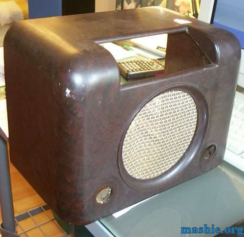 I wonder what it has been up to for the last 20 years, it was anything but clean. Except for the dirt it was in an excellent condition, no cracks or damages anywhere.
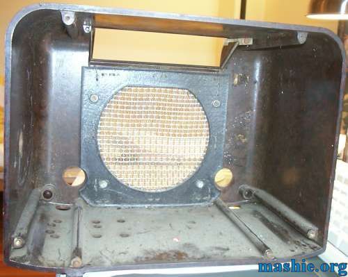 The inside was full of dead bugs, wasps and other nasty things. The speaker grille was removed and the bare case had to stay in the sink over night to dissolve all dirt.
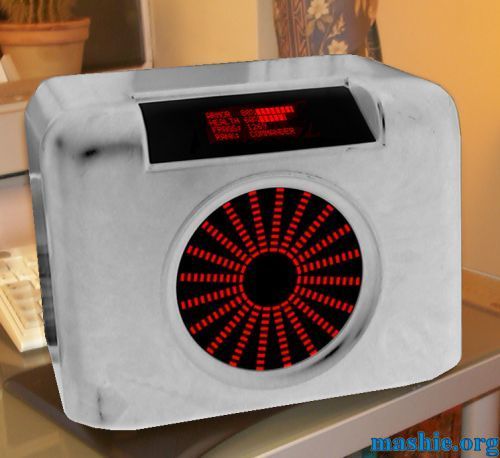 With the case cleaned I took a photo and did some editing to give a little idea of how the end result might look like. I also played around with different shapes of the spectrum analyzers. This was the design I preferred. I did some careful measurements of the case to help the planning of the remaining system. The shell is tiny: 305mm (12") wide, 182mm (7.2") wide and 232mm (9.1") deep. The selection of motherboard was simple though, only the Shuttle FV-24 could fit inside.
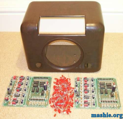 The Velleman K4300 kits arrived. I started with the easy part, soldering on all the components on the circuit boards. It wasn't very difficult but it took a weekend since each board had about 100 components.
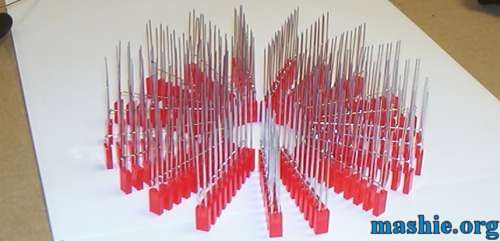 Now I had to figure out how to solder 200 LEDs in a circular pattern without a PCB. Easy, just solder them one by one to tinned copper. Bad idea, didn't work at all. I had to build a small jig so the LEDs would stay in place and also so the wire wouldn't roll away. After some trial and error including killing ten or so LEDs I had found a working procedure. They were soldered ten by ten in the first stage as you can see above.
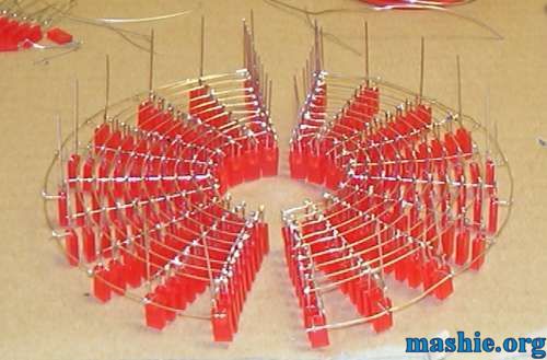 Time for the round wires, no jig used this time, I simply soldered the soon to be outer ring as a straight line. Had to dust off my math knowledge and calculate how much 1/20th of the outer circumference would be, that was the distance between each "LED bar". Then just solder the two ends together and a ring was created. Next step was to solder the inner ring. When I was happy with the inner and outer ring I added the remaining eight rings...
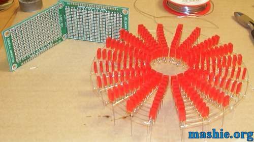 The PCBs supplied with the kit are at the top left corner and wire mesh, mashie style at the bottom right.
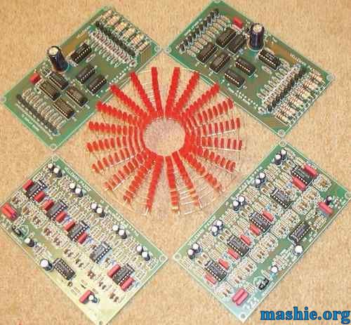 The result after two very productive weekends with the soldering iron.
I had to test to see if they worked before I could continue so here is an animated gif from the first ever test run (100k). 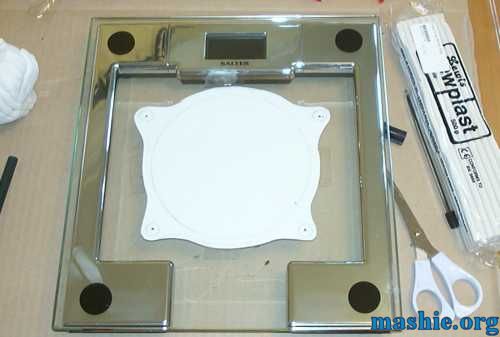 It is not easy to mount square LEDs in a panel so a different solution was needed. Time to embed the LEDs in a nice protective plastic block. Clear cast resin was bought from 4D - The Model Shop. I made a paper cutout of the desired shape and mounted it under a piece of glass to get a nice flat surface to use as bottom of the mould. A bathroom scale had to do this time.
 To keep the resin in place, a frame out of Plasticine clay was made.
|
| All trademarks used are properties of their respective owners. All rights reserved Copyright © 2002 - 2020 by Mashie Design |


